2.3.2 Injectors
After passing through the purification traps, helium enters the injector where it acts as the mobile phase and helps “push” the analytes through the analytical (separation) column. A variety of injectors are used in GC, but this text is concerned with the most common, a split-splitless injector. This type of injector can be used in two modes. For solutions containing extremely concentrated levels of analytes (in the parts per thousand or percent level as is encountered in synthesis operations), the injector is operated in the split mode. In this mode only a small fraction of the 0.2 to 1 μL of solution injected actually enters the separation column and the majority of the sample is vented to the atmosphere. The high concentration of analytes in the solvent allows for adequate identification and quantification. For solutions containing lower levels of analytes (parts per million and parts per billion), the injector is operated in a dual or splitless-split mode. Upon injection of a sample, the injector is operated in a splitless mode where all of the injected volume is being pushed onto the column. But if this mode of operation is allowed to continue throughout the chromatographic run, the peaks will be non-symmetrical (they will tail or be skewed) which will interfere with peak integration because of a continual addition of solvent molecules entering from the injection port. To avoid this problem, the split mode is switched on approximately 30-60 seconds after injection. This splitless-split mode allows the majority of the sample to “load” onto the column while clearing out the remainder of the sample to allow for a “clean”, well-shaped chromatographic peak. A typical split-splitless is shown in Animation 2.1.
Animation 2.1 Illustration of the Spiltless-Split Mode of Injection.
A few more points need to be made about the injector inlet. The interface between the atmosphere and the injector is separated by a septum such as the ones shown in Figure 2.6. Septa are manufactured out of various materials, all of which must be inert to leaching organic constituents into the GC or are coated on the GC side of the septum with Teflon. Septa are inexpensive and are routinely replaced, usually after 30 to 50 injections.
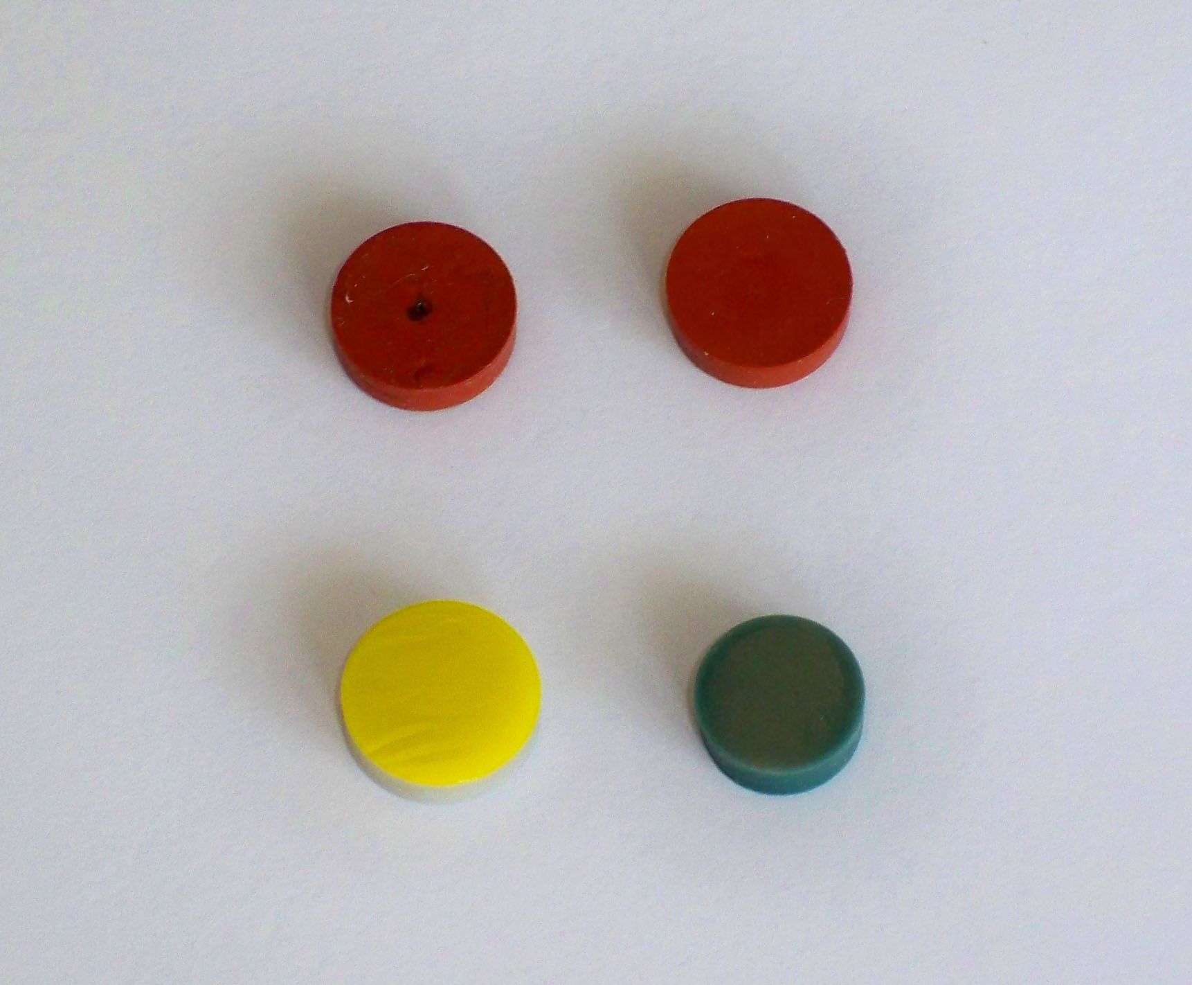
Figure 2.6 GC Septa. Note the puncture holes in the top left septum. The lower left septum contains a Teflon coating (yellow). The septa shown here are about 1 cm in diameter.
Samples are injected through the septa and enter a glass liner in the injection port. The purpose of the glass inserts (liners) is to avoid exposure of the analytes to reactive hot metal surfaces such as those contained in an unlined injector. Inserts come in a variety of forms. All liners contain a hole in the top to allow entry of the injection needle, a wider middle space for the expansion of liquid solvents into the vapor phase, and a hole in the bottom for insertion of the capillary column. Glass wool is usually present in the glass insert to keep pieces of the septum from blocking the inlet of the capillary column and to trap non-volatile components of the sample. Figure 2.7 shows two common injector inserts, one with the glass wool in the middle and one with the glass wool at the end.
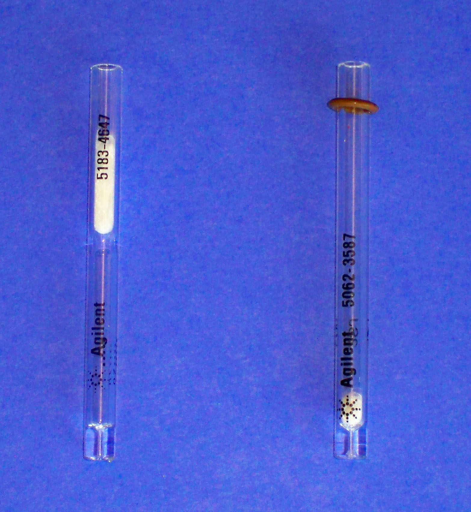
Figure 2.7 Injection Glass Inserts. The insert on the right shows the o-ring that seals the injection chamber and forces carrier gas through the column.
As noted earlier, samples are typically introduced into the GC with a glass syringe with a metal needle. Samples can be injected manually or with an automatic sampler. Standard 10-μL syringes are shown in Figure 2.8.
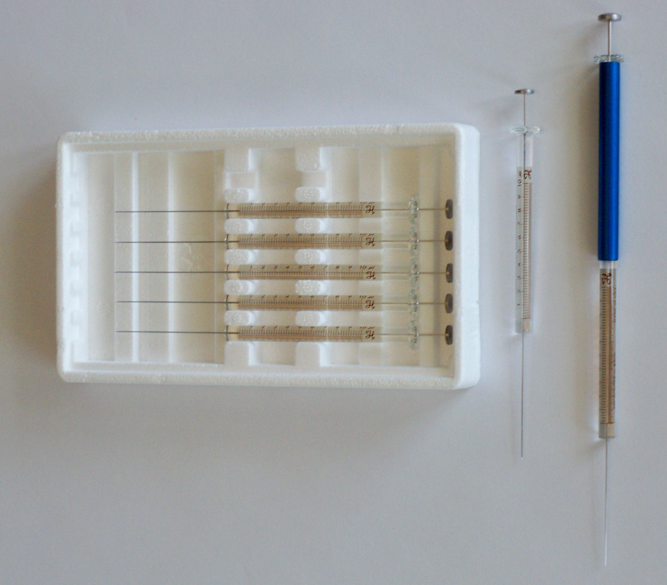
Figure 2.8 GC Injection Syringes.
All connections in GCs, from the carrier gas cylinder to the detector are made with Swedge Lock (a.k.a. Swagelok) fittings that seal the connections at high gas pressure. These fittings consist of a threaded nut, back ferrule, and front ferrule, all placed around a piece of tubing (refer to Figure 2.9). Fittings come in Teflon, stainless steel, and copper and in a variety of sizes ranging from smaller sizes for capillary columns as small as 0.2 mm to 6.0 mm packed columns. Ferrules are also available in graphite and in a variety of advanced materials such as Vespel, a composite of graphite and ceramic. A gas-tight fitting is achieved by tightening the nut and compressing the ferrule around the metal tube. A selection of ferrules and how they fit around a piece of tubing is shown in Figure 2.9.
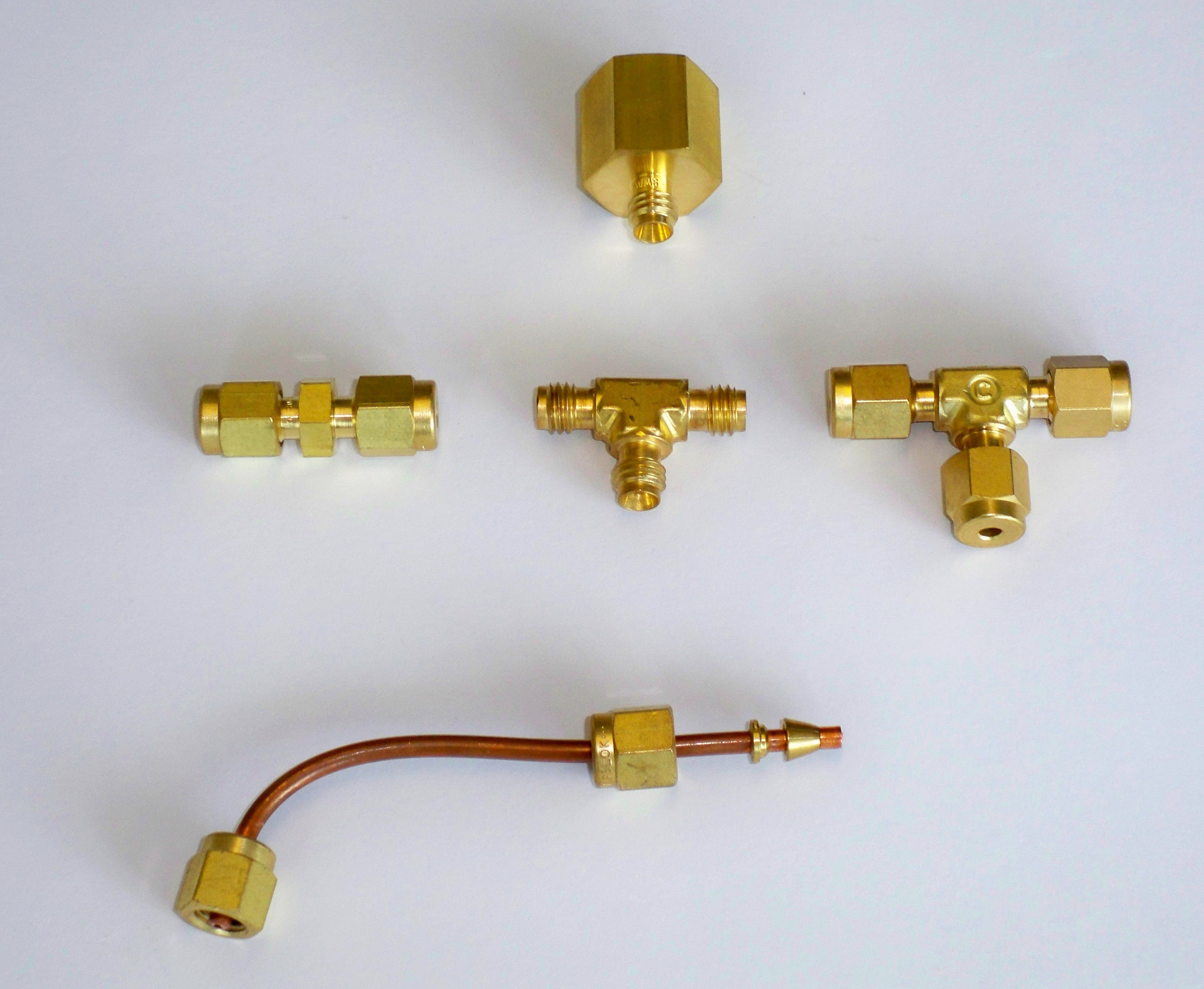
Figure 2.9 Swedge Lock Fittings.
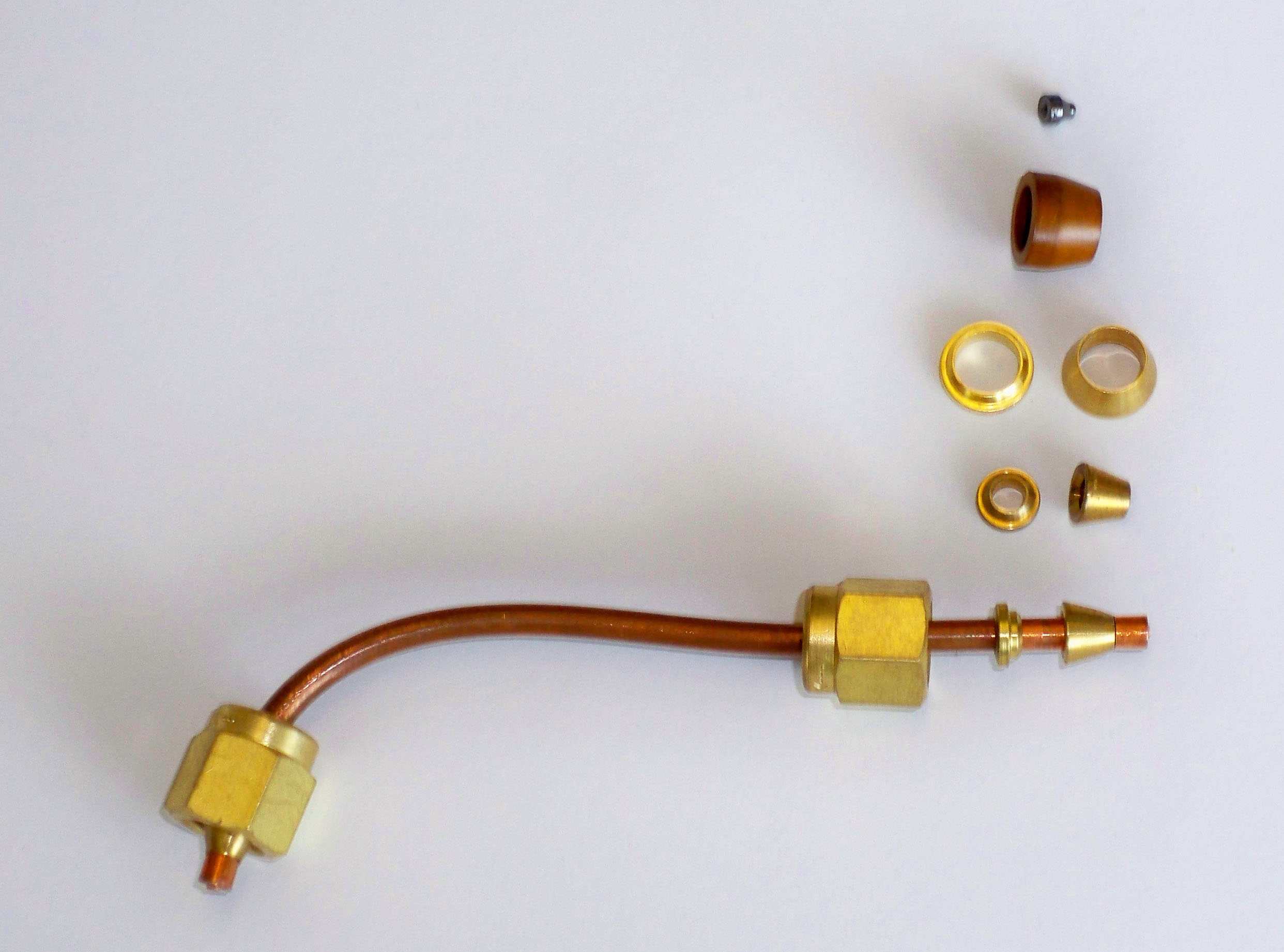
Figure 2.10 Several Types of Ferrules.
In addition to the split-splitless injector, other types of injector systems are available including an on-column injector and a cryogenic focusing injector. In the past, when packed columns were used, most injections were made directly onto a section of the column that did not contain any stationary phase resin. This concept has been extended to capillary column technology by using a wide-bore column (typically 0.5 mm in diameter or greater). A syringe with a very narrow capillary column needle (0.2 mm in diameter) is placed through a special port at the head of the injector and liquid samples are placed directly onto the column. The needle is withdrawn, the injector port is sealed and the chromatographic run is started. On-column injection avoids exposing the analytes to any reactive surfaces.
Highly volatile analytes, normally not separated by standard GC conditions can be analyzed using a cryogenic focusing injector. Here, gas or liquid samples are injected through a septum, but the bottom of the injector contains a cryogenic fluid (liquid N2) around the head of the capillary column. The cryogenic fluid cools the column and causes the analytes to condense at the head of the column. After injection, the cryogenic fluid is removed, the column oven slowly heated, and the volatile analytes are analyzed.
With today’s extremely small injection volumes (0.2 to 1 μL), reproducibility of sample injection can be a problem. It is necessary to inject exactly the same volume of sample (to within three significant figures) to avoid introducing considerable error into the results. Two solutions have been devised for this problem: (1) automatic samplers/injectors and (2) internal standards. Mechanical automatic samplers can accurately and consistently reproduce small volume injections and save considerable labor costs (and time if you happen to be a graduate student or on a slim budget). A typical automatic sampler today can hold up to 100 samples and be programmed to run the samples in any order. This is more convenient than manually injecting a sample and waiting for the GC run to end, which can range anywhere from 5 minutes to hours. The automatic sampler allows the user to simply return hours to days later to find the samples analyzed and the data stored and ready for processing on the computer-controlled station. Automatic samplers are common features today even in graduate schools since they run hour after hour, day after day, with minimal oversight or maintenance. The typical cost of an automatic sampler is only $10,000 and they rapidly pay for their self in high sample volume work environments.
The second option for overcoming injection errors, an internal standard, is also common in capillary GC and is usually used in conjunction with automatic samplers. Internal standards were discussed in section 2.1 but will be repeated here due to its importance. An internal standard is a chemical (analyte) that is not originally present in any sample. Equal amounts of the internal standard are added to every sample and reference standard. The computer program in the control station can then be programmed to correct for injection errors. One way to use this technique is to average the peak area for the internal standard that is measured in every external standard and compare the area to that observed for each sample. If the internal standard measured in a sample falls below or above this average due to a poor injection, the computer will automatically adjust the areas of every peak in the chromatogram accordingly. By using a combination of automatic injectors and internal standards, highly accurate and consistent results can be obtained.
| Frank's Homepage |
©Dunnivant & Ginsbach, 2008