3.3 Components of an Inductively Coupled Plasma—Atomic Emission Spectrometry System (ICP-AES)
3.3.4 Separation and Detection
After the atoms are excited or ionized in the plasma, they exit the high temperature region and electronically relax. This results in the emission of at least one element-specific photon available for detection. The first choice to be made by the analyst is the position of the monochromator entrance relative to the plasma source. Two choices are available, axial and radial alignment. A radial design allows photons to move from the side of the plasma (at the end of the torch) to the entrance slit while an axial design gives higher intensities (and better detection limits) since the photons come from the center and end of the plasma. Thus, depending on the concentration of analytes in a given sample, the analyst may choose to monitor the emissions from the radial angle for higher concentrations; this avoids burning out the detector, which is costly to replace. Or the analyst may choose to use the axial monochromator alignment for lower concentration samples. Changing the angle of observation can potentially avoid additional sample preparation such as dilutions. Many brands of instruments allow a selection between radial and axial monitoring.
Three broad categories of detection are available for analyzing the emitted photons: sequential, simultaneous multi-channel, and Fourier transform systems. In the first two, all wavelengths enter a monochromator where they are dispersed by prisms and/or grating monochromators and are then transmitted to the detector (most commonly the PMT presented in Animation 2.4, or a CCD presented in Figure 2.9). Fourier transform systems produce spectral separations by capitalizing on constructive interference techniques as first developed for Michelson’s interferometer in 1881. In Fourier transform systems, no slits or monochromators are required, and this creates better detector limits because more intense radiation reaches the detector. Fourier transform systems also have higher spectral resolution (and thus have fewer spectral interferences) and can simultaneous monitor all wavelengths for longer times. This text will only cover sequential and simultaneous multi-channel systems that use monochromators because Fourier transform systems extend past the basic ICP instrumentation goal of this Etextbook and are considered “higher end” systems.
The first ICP-AES systems used a sequential monochromator to separate the analyte-emitted photons by wavelength before detecting them with a single detector. This approach is analogous to the FAES system where only one element could be analyzed at a time. In a sequential system, if a sample needed to be analyzed for multiple elements, the grating system was rotated to direct the appropriate wavelength to the exit slit of the monochromator and into a PMT (described in Section 2.2.9). While ICP-AES provided superior detection limits compared to FAES instruments, it was just as slow and labor intensive as FAES.
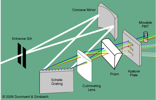
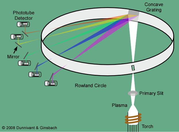
Simultaneous multi-channel systems rapidly became economical as component production costs decreased and as labor costs have increased with time. In these systems, multiple elements can be detected at the same time using one of two designs. One way is to use a standard grating monochromator that separates the photons based on wavelength and directs the photons of interest to specific exit slits. Then, a single detector was rapidly moved from one slit to the other to analyze photons of various wavelengths. This type of system is shown Figure 3-6. Another way to accomplish multiple element detection is by placing an individual detector, again usually a PMT, at each exit slit. Such a system, the Rowland circle, was shown in Figure 3-1 and is shown again here as Figure 3-7. The Rowland design increases the upfront cost of an instrument and the running cost as PMT are replaced but this design significantly decreases the analysis time.

Figure 3-6. A Single Detector (sequential type monochromator) ICP-AES System.

Figure 3-7. A Rowland Circle ICP-AES System.
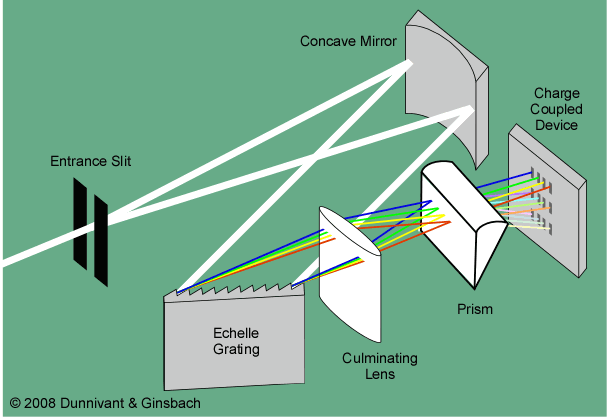
More recent advances, use a combination of two monochromators (one prism and one Echelle grating, or one conventional grating monochromator and one Echelle grating), remove the exit slit, and place a multiple element detection system, such as a charge coupled device (CCD described in Section 2.29, Figure 2-9) or charge injection device (CID described in Section 2.29, Figure 2-9) in the path of the separated wavelengths (refer to Figure 3-8).

Figure 3-8. A Multiple Monochromator ICP-AES Instrument.
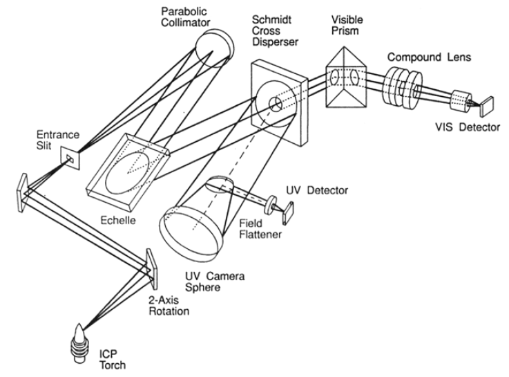
Some instruments use one detector for UV wavelengths and another for visible wavelengths. There are a variety of designs for these latter systems illustrated below. These more advanced instruments have an increased cost but are more economical recently due to decrease in the production costs of CCDs and CIDs versus PMTs. They also significantly reduce the lab bench space requirements. Instruments such as the one in illustrated in Figure 3-9 (1) offer superior resolution compared to a Rowland circle due to the advance monochromator systems, (2) offer the immediate option to monitor secondary or greater diffraction that can be used in high concentration samples, (3) reduce the size of the instrument due to the reduced size of the detector(s), and (4) offer more inexpensive instruments as the cost of CCDs and CIDs become more economical.

Figure 3-9. A Dual Echelle Grating – Prism Monochromator ICP with Dual CCD Detectors. From Barnard et al., Anal. Chem., 1993, 65, 1231. Reprinted with permission from ACS.
| Frank's Homepage |
©Dunnivant & Ginsbach, 2008