1.3.2 Diffraction
Diffraction is a process in which a collimated beam of radiation spreads out as it passes (1) though a narrow opening or (2) by a sharp barrier. An interesting distraction effect was observed in a laboratory setting by Thomas Young in 1801 when he performed the two-slit experiment (discussed below). Because diffraction depends on the wavelength of light, it can be used to separate polychromatic light (white light) into its constituent optical frequencies; in the case of white light, this would result in a rainbow of colors. The manipulation of diffraction forms the basis of selecting a narrow range of wavelengths of light in a monochromator.
In order to more easily understand how diffraction can be used to disperse wavelengths, picture the passage of radiation through a narrow barrier. Figure 1-7 illustrates such a barrier. As the slit width narrows waves of radiation spread out more strongly. The Heisenberg Uncertainty Principle indicates that as the uncertainty in the position of a photon decreases (in a direction transverse to its propagation direction), the uncertainty in its transverse momentum must increase; this uncertainty in transverse momentum is what causes the light to spread out. When the slit is sufficiently wide, the diffraction is small because there is still great uncertainty in position (Figure 1-7a). As the slit becomes more narrow (Figure 1-7b), the uncertainty in position becomes smaller which results in greater diffraction.
Figure 1-7. Variation in Slit Width Openings.
Diffraction is intimately related to the constructive and destructive interference of waves. Start by considering monochromatic electromagnetic radiation passing through two slits (Figure 1-8). The monochromatic light is passing through one narrow slit before being passed through two more slits. As radiation is passes through the second slits, diffraction occurs at both slits creating two beams that spread out and overlap. Constructive and deconstructive interference between these beams can be observed on a flat plate (a detector in this case). Regions on the detector in which the path length difference between these two waves is an integer multiple of the wavelengths constructively interfere and produce a large intensity. Positions on the detection plate that correspond to odd integer multiples of half a wavelength create deconstructive interference, with no resulting intensity. Overall the intensity distribution on the detector varies sinusoidally, with high intensity corresponding to constructive interference, and zero intensity corresponding to destructive interference. Each of these situations is illustrated in Figure 1-8. If the two slits are replaced by many narrow, equally spaced slits (i.e. a diffraction grating) the regions of constructive interference become very narrow. Instead of a sinusoidal variation in intensity, a series of narrow bright bands appears on the detector.
Figure 1-8. An Idealized Illustration of the Two-Slit Experiment Illustrating the Constructive and Deconstructive Nature of Electromagnetic Radiation. Distinct bands are show here for illustrative purposes only; the bands are actually broader areas of light (constructive interference) that gray to areas with no light (deconstructive interference). The blue lines above correspond to the alignment of maximum constructive interference.
The above discussion was for monochromatic radiation. If the concepts in Figure 1-8 are extended one step further and polychromatic light is used, the different colors of radiation are separated. All of the different wavelengths will constructively interfere in the center of the detector. However, since each color has a specific wavelength, the locations of the other interference maxima depend on the wavelength. As a result, two “rainbow” spectra of light will be centered around the top and bottom constructive interference lines shown in Figure 1-8.
While the diffractive properties of multiple transmissive slits could be utilized in analytical instruments, this would result in the creation of very narrow, but long instruments. As a result, mirrors that also create diffraction are utilized to make instruments more compact. They do this by bending light at a sharp angle, as observed below in the case of reflection grating monochromators. The principle is the same as a transmission grating; each of the sawtooth shaped steps in Figure 1-9 (referred to as a blazed surface) acts as a “slit”. Waves are diffracted off of each of these slits, and wavelength dependent constructive and destructive interference creates a rainbow spectrum in reflection. Monochromatic light is used for illustration purposes here to lessen the complexity of the figure. However the principles discussed below for a single wavelength apply to a mixture of wavelengths.
Figure 1-9 Diffraction Resulting from a Echellette (Conventional) Grating.
Typically radiant waves constructively interfere in two directions (+1 and -1) depending on the incident angle of incoming radiation and the grating spacing d. These two directions are analogous to the upper and lower constructive interference bands in Figure 1-8. There is one more complication that has been added to Figure 1-9, in Figure 1-8 incident radiation was perpendicular to the slits (parallel to the grating normal), whereas in Figure 1-9 incident radiation makes an angle i with respect to the grating normal (the dashed vertical line in Figure 1-9). Radiation will be diffracted to the left and to the right of the grating normal; these will be mathematically characterized below separately for two types of grating surfaces. The left-of-normal diffraction will be discussed first (the left-hand figure). The lower right-hand diagonal lines 1 and 2 are incoming monochromatic radiation and the upper right-hand diagonal lines 1’ and 2’ are the diffracted monochromatic radiation.
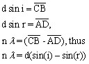
The basis of the following derivation is that in order for constructive interference to occur the pathlength differences between waves from adjacent slits must be an integer number of wavelengths. Before beginning the derivation it is first necessary to define the problem and parameters. The line “d” is the distance between corresponding points on each grating line (a grating surface contains numerous blazed parallel lines of reflective material, in this case points A and B). Line segments AC and AD are the distances at 90-degree angles from the point of diffraction to the diffracted wave on the next grating surface (parallel ray). The maximum constructive interference will occur at the diffracted angle “r” where the path length difference between rays 1 and 2 is an integer number of wavelengths. As shown in Figure 1-9, ray 2 travels a greater distance than ray 1 and the difference in the paths is equal to the addition of line segment distances CB and BD. Again, in order for constructive interference to occur, the path difference (CB + BD) must be equal to the wavelength times an integer (n, not to be confused with the index of refraction), thus
![]()
The integer n is referred to as the diffraction order and λ is the wavelength of interest. Observe that the angle of CAB is equal to angle “i” and the angle DAB is equal to “r”. From basic trigonometry principles, we obtain

where d is the distance between points A and B on two adjacent blazed surfaces. By substituting these two-line segment equations into the previous equation, we obtain the governing equation correlating the angle of reflection to wavelength
![]()
This is called the grating equation.
A similar diffraction pattern can occur in the opposite direction (to the right in Figure 1-9). As drawn in this figure, the low blazing angles will result in a higher intensity of reflected light to the right as compared to the light reflected in the left-hand side of Figure 1-9; this occurs due to the ordinary angle of reflection off of each surface being equal to the diffraction angle, and the intensity is maximized. In this case, illustrated in the right-hand side of Figure 1-9, rays 3 and 4 entering from the left are reflected at the surface angles i plus r. Using line segments A’, B’, C’, and D’ a similar mathematic derivation can be made for the constructive interference shown by lines 3’ and 4’ as was made earlier for the left-hand side of Figure 1-9. This can also be derived by noting that the interger n, can have plus or minus values of 1.
Thus, constructive interference can occur at a negative and a positive angle, relative to the normal plane, and is indicated by a plus and minus sign in the governing equation, respectively.
![]()
A positive sign results when the incident and diffracted beams are on the same side of the grating normal line (the vertical line in the middle of each grating), with the converse for a negative sign. It should be noted again that the angle of diffraction is highly dependent on the angle of the incoming incident radiation and the wavelength of radiation. This will be important when different types of grating monochromators are discussed in Chapter 2.
The diffraction pattern illustrated in Figure 1-9 for monochromatic light is the same concept as that illustrated for the two-slit experiment described in Figure 1-8. Both the slit and each individual blaze behave as point sources of light. Both systems cause constructive interference when radiation from each blaze or slit travels the same distance or a distance that is an integer multiple of the wavelength (nλ). When polychromatic light is reflected by a grated surface as shown in Figure 1-10, a “rainbow” dispersal of wavelengths would occur on the surface of the detector. Subsequently, each wavelength of the rainbows is collimated with a collimating mirrors (or lens) and focused onto a sample container or instrumental component, such as the entrance slit to a detector.
Figure 1-10. Separation of White Light by a Grating Monochromator.
Further analysis of the governing equations given above indicates that several wavelength solutions exist for each diffraction angle r, depending on the integer n, referred to as the order of diffraction. The first wavelength, referred to as first-order diffraction is (n=1), is always the longer wavelength (i.e. 400 nm), with second-order diffraction being half the wavelength (i.e. 200 nm), and so on. Fortunately for our purposes of obtaining as pure radiation as possible (with respect to wavelength) usually more than 90% of the incident intensity is first-order diffraction. When second-order and third-order diffraction is a problem these wavelengths can be removed with a secondary filter or second monochromator (as presented in Chapters 2 and 3). In some cases, such as in the presence of high concentrations of analyte, second- and third-order diffraction is used for quantification since the corresponding wavelength is less intense and will not damage the detector.
For an Echellette grating, high dispersion (separation of wavelengths, which is desired) is obtained by making the groove width d as small as possible (having a high number of grooves or blazes) and by making the focal length large (the focal length is the distance between the monochromator or the focusing lens and the exit slit). However, achieving high dispersion is difficult since a large focal length results in a reduction in light intensity and dense gratings are relatively expensive to produce. Improvements in resolution result if the blaze angle is made steeper (called an Echelle-style grating), and a correspondingly large value for the diffraction order (n~100) is used. In the typical Echelle grating configuration the angles r and i (in Figure 1-9) are now approximately equal, and r or i is represented by β. For this situation, the governing equation reduces to
![]()
The Echelle grating achieves higher dispersion while maintaining high diffraction intensity by making the angle β and the order of diffraction (n) large (i.e. by increasing the blaze angle and diffraction order). Echelle gratings have fewer blazings (grooves) than Echellette gratings. Again, while the previous normal grating resulted in first, second, and third order diffraction (n=1,2,3), n values for an Echelle are much larger (75th to over 100th ). For example, as shown in Table 1.3, a diffraction order of 1 for a normal grating correlates to n=75 for an Echelle grating. This higher order of diffraction is selected for by increasing the blaze angle to maximize the reflection of radiation at the 75th order of diffraction. This results in superior resolution of spectral lines over conventional grating systems. For example in a conventional grating the emission lines of Zn (at 202.55 nm) and Mg (at 202.58) overlap and cannot be resolved. In the Echelle grating, considerable baseline resolution is achieved for these two spectral lines.
Table 1.3. Comparisons of Figure of Merit for Echellette and Echelle Grating Monochromators.
| Feature | Echellette (Conventional) Grating | Echelle Grating |
| Focal length (m) | 0.5 | 0.5 |
| Groove density (grooves/mm) | 1200 | 79 |
| Angle of diffraction | 10o 22' | 63o 26’ |
| Width of grating (mm) | 52 | 128 |
| Order of 300 nm | 1st | 75th |
| Resolution at 300 nm | 62 400 | 763 000 |
| Linear dispersion at 300 nm (mm/nm) | 0.61 | 6.65 |
| Reciprocal linear dispersion at 300 nm (nm/mm) | 1.6 | 0.15 |
| f-number | f/9.8 | f/8.8 |
Source: Keliher and Wohlers, Anal. Chem., 1976, 48, 333A
Echelle grating monochromators can produce highly pure spectral separations of radiation; these will be used in applications in the next two chapters where a combination of dispersive devices (prisms, Echelle, and Echellette gratings) are used to separate wavelengths of light. The use of an Echelle grating will allow more powerful imaging and detectors to be used in emission spectrometry where spectral overlap can be a problem. The wavelength separations in combined gratings systems are nearly as pure as the emitted radiation from a hollow cathode lamp, which will minimize most spectral interferences from the flame emissions or from the absorption and emission of other elements in the sample. Grating monochromators are the heart of modern absorption (AAS) and emission (AES) instruments.
| Frank's Homepage |
©Dunnivant & Ginsbach, 2008